1. Basic Knowledge of Projection
-
Central Projection: The light source emits from the projection center.
-
Orthographic Projection: When the projection rays are parallel and perpendicular to the projection plane, the resulting projection on the projection plane is called orthographic projection.
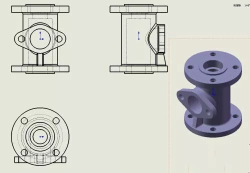
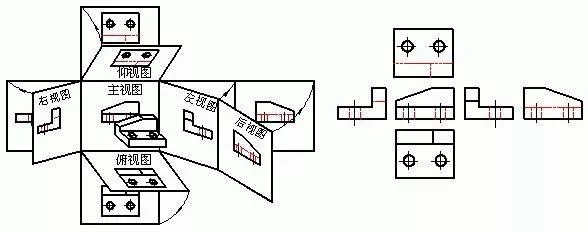
2. Three Views
The three main projections of an object form a view that accurately reflects the object’s length, width, and height dimensions. This engineering drawing (comprising the front view, top view, and left view) is an established abstract representation of the object’s geometric shape in engineering.
-
Front View:
- Select the direction that best reveals the object’s features as the projection direction for the front view.
-
Top View:
-
Left View:
-
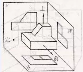
Summary of Projection Surface Expansion:
- Projection rules are as follows:
- Front and top views: Length aligns.
- Front and left views: Height aligns.
- Top and left views: Width is equal.
- In summary: Length aligns, height aligns, width is equal.
- Projection rules are as follows:
-
Projection Characteristics of Planes and Lines on the Object:
- Tilted to the projection plane: Contracting.
- Perpendicular to the projection plane: Converging.
- Parallel to the projection plane: Authentic.
3. Various Methods of Expressing Parts
There are several methods to express the shape of parts:
-
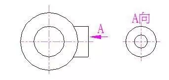
Basic Views:
- Basic views include front, top, left, right, bottom, and rear views.
- Place the basic views on one sheet of paper according to their layout without labeling the view names. If needed, indicate the view name “X direction” above the view and use arrows to specify the projection direction with the same letter nearby.
-
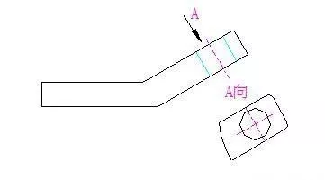
Inclined View:
- When a surface of the part is tilted relative to the projection plane, an auxiliary projection plane parallel to the surface is added, and the resulting view is called an inclined view.
- When a surface of the part is tilted relative to the projection plane, an auxiliary projection plane parallel to the surface is added, and the resulting view is called an inclined view.
-
Partial View:
- The view obtained by projecting a specific part of the component onto the basic projection plane is called a partial view.
- The view obtained by projecting a specific part of the component onto the basic projection plane is called a partial view.
-
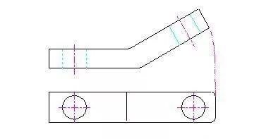
Revolved View:
- When the inclined part of a component has a clear axis of rotation, imagine rotating this part parallel to a selected basic projection plane and then projecting onto that plane.
- When the inclined part of a component has a clear axis of rotation, imagine rotating this part parallel to a selected basic projection plane and then projecting onto that plane.
-
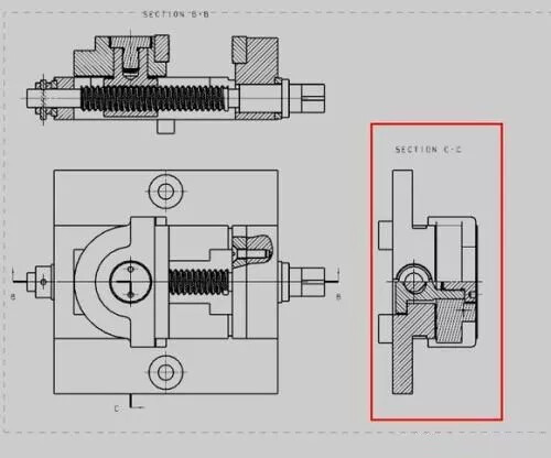
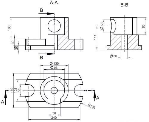
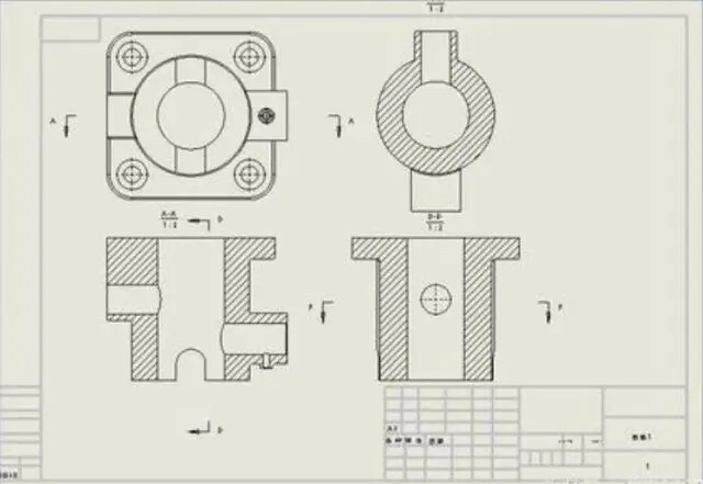
Sectional View:
-
For components with complex internal structures, where hidden lines would increase, a hypothetical cutting plane is used to section the part, projecting the remaining visible portion.
-
Types of Sectional Views:
- Half Section: Used to express the external shape and internal structure of symmetric objects (divided by a symmetry line).
- Local Section: Used to express the internal shape of a part while retaining most of its external shape (local sectioning).
- Stepped Section: Multiple parallel cutting planes are used to create a stepped section.
-
-
Coinciding Section:
- Used to express the cross-sectional shape of a local structure of the part.
-
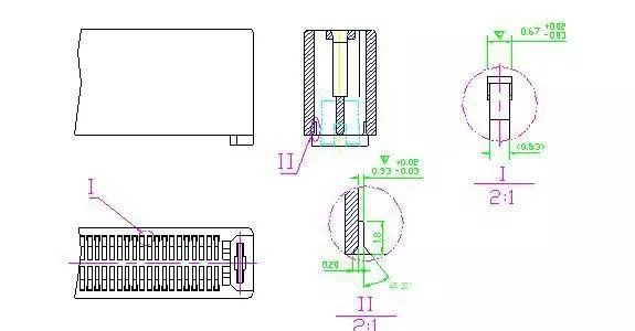
Local Enlarged View:
4. Basic Steps in Drawing
- Determine the drawing size and scale (product size and structure).
- Draw the frame according to specified dimension requirements.
- Plan views: Distribute views based on product size and structural complexity, especially the number and distribution of sectional views and technical requirement locations, leaving space for the title block.
- Analyze the product and draw.
- Dimension labeling.