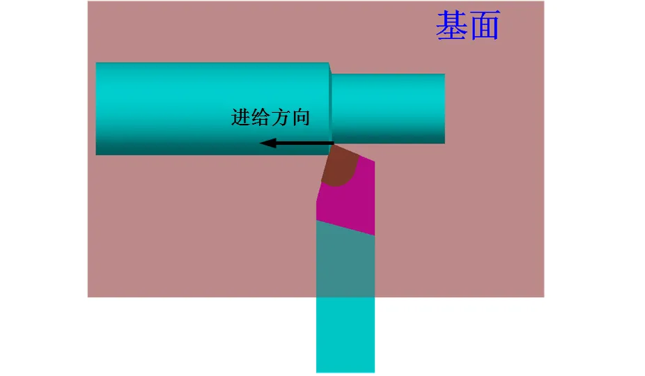
When cutting metal, the tool’s angle during its entry into the workpiece is an important parameter that determines the geometric shape of the tool’s cutting part.
1. Composition of the Cutting Part of a Lathe Tool
Three Surfaces, Two Edges, and One Tip
The cutting part of a lathe tool consists of the front face, main flank, secondary flank, main cutting edge, secondary cutting edge, and the tip.
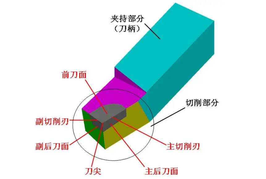
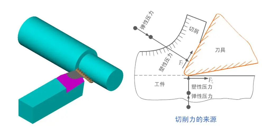
- Front Face: The surface on the tool where the chips flow over.
- Main Flank: The surface on the tool that faces the machined surface of the workpiece and interacts with it.
- Secondary Flank: The surface on the tool that faces the already machined surface of the workpiece and interacts with it.
- Main Cutting Edge: The line where the front face meets the main flank is known as the main cutting edge.
- Secondary Cutting Edge: The line where the front face meets the secondary flank is known as the secondary cutting edge.
- Tip: The intersection of the main and secondary cutting edges is referred to as the tip. The tip is actually a small segment of a curve or line, called a rounded tip or chamfered tip.
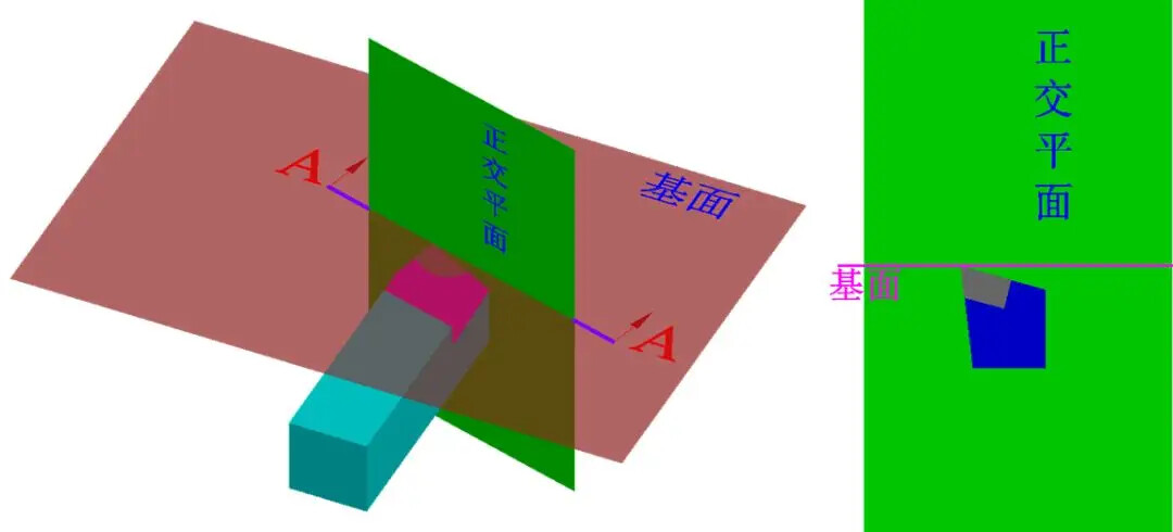
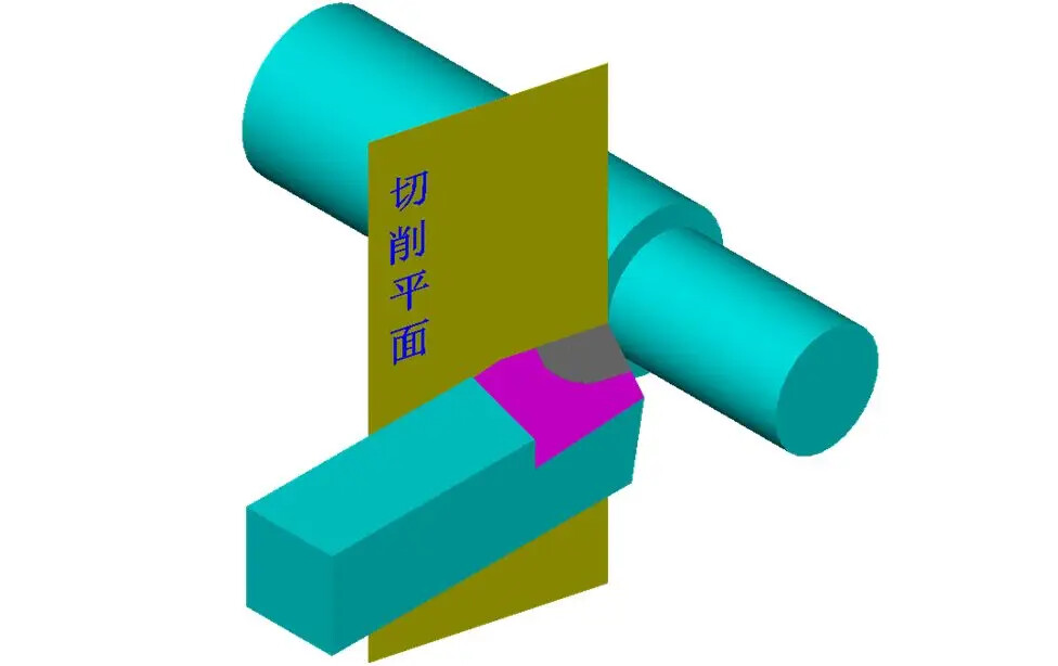
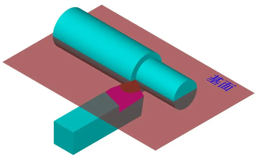
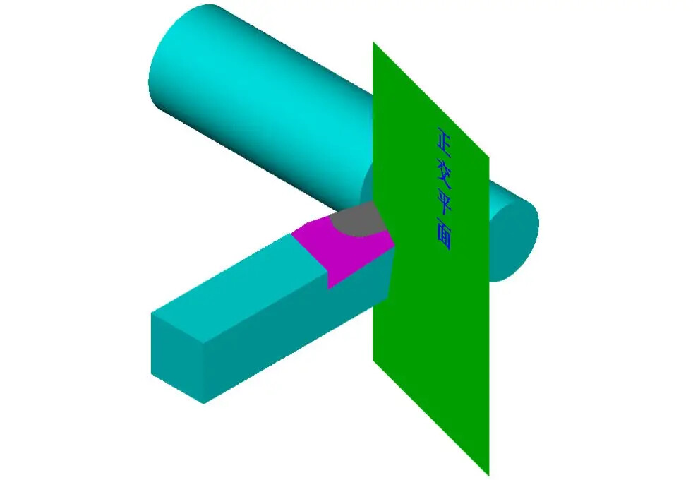
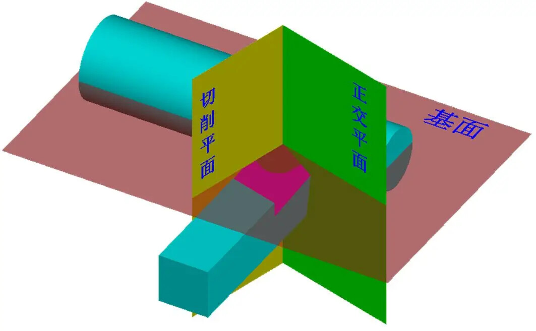
2. Auxiliary Planes for Measuring Cutting Angles
To determine and measure the geometric angles of the lathe tool, three auxiliary planes are selected as references: the cutting plane, base plane, and orthogonal plane.
-
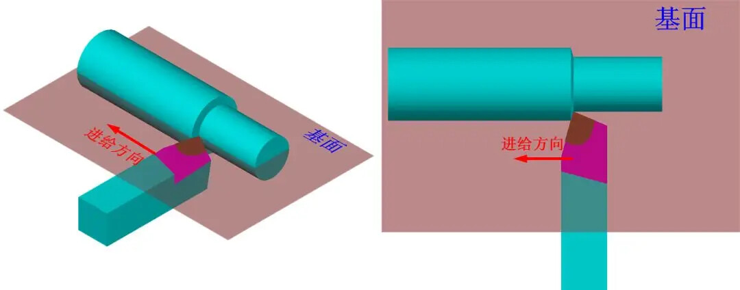
Cutting Plane: A plane that intersects the main cutting edge at a selected point and is perpendicular to the bottom plane of the tool holder.
-
Base Plane: A plane that passes through a selected point on the main cutting edge and is parallel to the bottom plane of the tool holder.
-
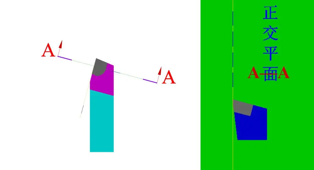
Orthogonal Plane: A plane that is perpendicular to both the cutting plane and the base plane.
These three coordinate planes are mutually perpendicular, forming a three-dimensional Cartesian coordinate system.
3. Main Geometric Angles of the Lathe Tool and Their Selection
-
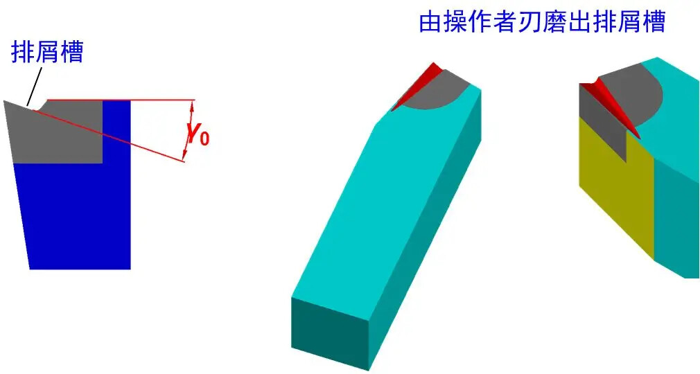
Front Angle (γ0) Selection Principle: The size of the front angle primarily addresses the balance between the strength and sharpness of the tool tip. Generally, for materials with high hardness, a smaller front angle is chosen, while for softer materials, a larger angle is preferred. Additionally, for rough machining, a smaller front angle is used, and for finishing, a larger angle is selected. The front angle is typically chosen between -5° and 25°.Usually, during the manufacturing of lathe tools, the front angle (γ0) is not pre-made but is achieved by grinding a chip fluting on the tool. This fluting, also called a chip breaker, serves to break chips to prevent entanglement, control the direction of chip flow, maintain the precision of the machined surface, reduce cutting resistance, and prolong tool life.
-
Back Angle (α0) Selection Principle: The first consideration is the nature of the machining. For finishing, a larger back angle is chosen, while for roughing, a smaller angle is selected. The hardness of the material also plays a role; for harder materials, a smaller main back angle enhances the strength of the tool tip, whereas for softer materials, a larger angle may be selected. The back angle should not be zero or negative and is generally chosen between 6° and 12°.
-
Main Inclination Angle (Kr) Selection Principle: The rigidity of the turning process system, consisting of the lathe, fixture, and tool, is the primary consideration. If the system is rigid, a smaller main inclination angle is preferred to enhance tool life, improve heat dissipation, and surface finish. When machining steps, a main inclination angle of 90° is used, while for intermediate cutting, it is usually around 60°. The main inclination angle typically ranges from 30° to 90°, with common values being 45°, 75°, and 90°.
-
Secondary Inclination Angle (Kr’) Selection Principle: The tool, workpiece, and fixture must have sufficient rigidity to minimize the secondary inclination angle; otherwise, it should be larger. For finishing, a secondary inclination angle of 10° to 15° is suitable, while for roughing, around 5° is appropriate.
-
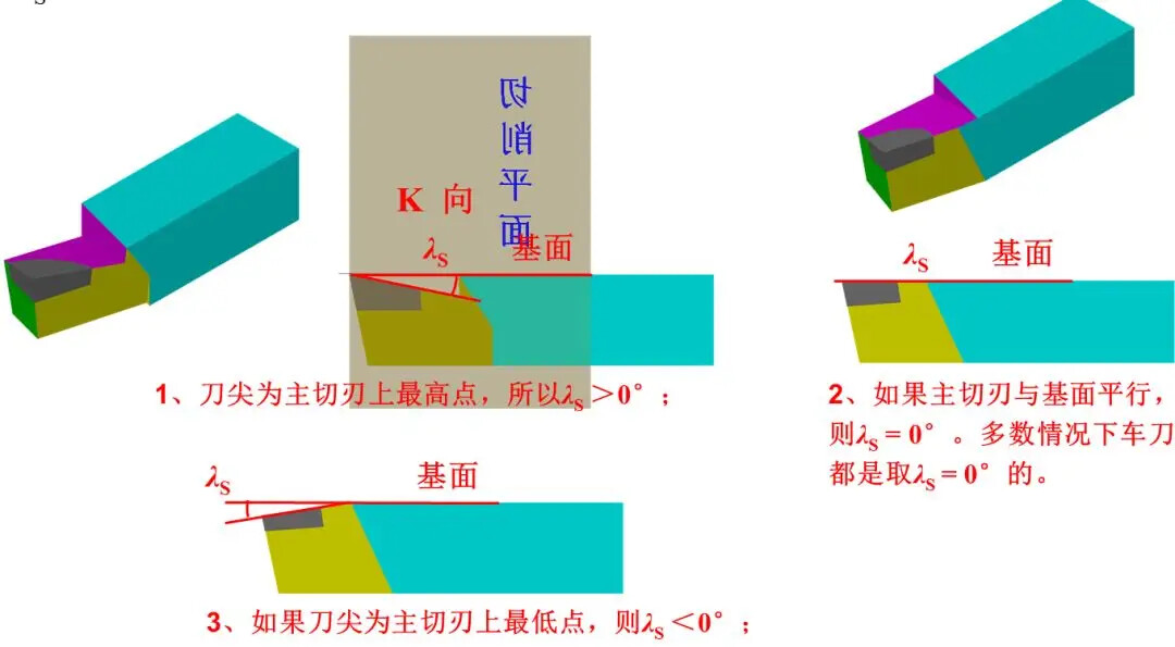
Edge Inclination Angle (λS) Selection Principle: This primarily depends on the nature of the machining. For rough machining, where the workpiece exerts greater impact on the tool, λS should be ≤ 0°. For finishing, where the impact is less, λS should be ≥ 0°. Typically, λS is set to 0°. The edge inclination angle is usually selected between -10° and 5°.