1. Basic Concepts
The Stress Intensity Factor (SIF) is a physical quantity that describes the stress field distribution around the crack tip. It characterizes the intensity of the stress field near the crack tip of an elastic material under external load. The concept of SIF was first introduced by Irwin in 1957 to quantify the degree of stress concentration at the crack tip, successfully explaining brittle fracture under low-stress conditions. In fracture mechanics, SIF is an essential parameter for predicting crack propagation and ultimate material failure. The physical significance of SIF lies in its ability to quantify the stress intensity around the crack tip and its direct relation to crack propagation behavior. When the SIF at the crack tip reaches a critical value, the crack will propagate unstably, leading to material fracture. Therefore, SIF is a crucial tool for assessing structural integrity and predicting material failure. In practical applications, SIF calculation typically involves factors such as crack geometry, material properties, and applied loads.
2. Theoretical Calculation Formula
In fracture mechanics, SIF is a key parameter used to predict the stress state near the crack tip caused by remote loads or residual stresses. Calculating the SIF helps assess structural integrity and predict material failure under stress. SIF is often compared with a material’s fracture toughness (Kc) to determine whether a crack will propagate. Fracture toughness is the material’s resistance to crack growth; when the SIF exceeds Kc, the crack will propagate uncontrollably, resulting in structural failure.
The SIF formula is:
K=\sigma \cdot \sqrt{\pi \cdot a} \cdot Y
where:
- K is the Stress Intensity Factor (unit: MPa√m),
- σ is the applied stress (unit: MPa),
- a is the crack length (unit: m),
- Y is the shape factor (dimensionless).
The shape factor Y is a dimensionless parameter accounting for the geometry of the crack and its orientation relative to the applied stress. Different crack shapes and loading conditions lead to different Y values. For example, Y is 1 for an infinite plate with a central crack, while for an edge crack, Y varies based on the ratio of crack length to plate width. Accurate SIF calculation is significant in engineering design and material selection. By calculating SIF, engineers can evaluate a material’s structural integrity and predict failure under various load conditions, leading to the design of more durable and safer structures.
3. Classification of Stress Intensity Factors
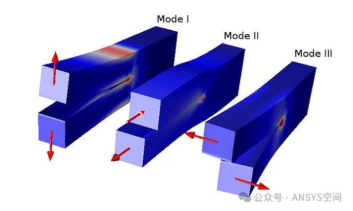
- Mode I: Opening Mode (KI) – Also known as tensile or opening mode, it is the most common crack propagation mode. Under Mode I, the tensile stress perpendicular to the crack surface causes the crack to open. According to Griffith’s theory, when the Mode I Stress Intensity Factor KI reaches the material’s fracture toughness KIc, the crack will begin to propagate.
- Mode II: Sliding Mode (KII) – In Mode II, sliding or shear stress causes the crack surfaces to slide relative to each other. The direction of crack propagation is perpendicular to the shear force at the crack tip.
- Mode III: Tearing Mode (KIII) – In Mode III, or anti-plane shear, the crack surfaces slide along the crack front under shear force. The crack propagation direction aligns with the shear force at the crack tip.
Mode I fracture is the most critical and is thus the primary focus in engineering.
4. Methods for Calculating Stress Intensity Factor
4.1 Analytical Method
The analytical method is a classical approach to calculating SIF, relying on analytical geometry and elasticity theory. This method is suitable for structures with simple geometry and load conditions.
- Applicable Conditions: The analytical method is suitable for simple crack shapes and load conditions, such as central and edge cracks, where a closed-form solution for SIF can be derived.
- Calculation Process: First, select an appropriate coordinate system and stress function based on crack geometry and load conditions. Then, use fundamental elasticity equations, such as displacement and stress equations, to derive the SIF expression. Finally, calculate the specific SIF value through mathematical operations.
- Pros and Cons: The analytical method offers accurate results and a solid theoretical basis. However, it is limited in scope, making it challenging to obtain closed-form solutions for structures with complex geometries and load conditions.
4.2 Finite Element Method (Recommended)
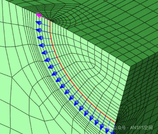
The Finite Element Method (FEM) is a numerical approach that discretizes a structure into a finite number of small elements, approximating stress and displacement distributions within each element to solve for SIF. Currently, software like ANSYS supports SIF calculations for various crack models in both 2D and 3D structures.
- Applicable Conditions: FEM is suitable for complex geometries and load conditions, including non-planar cracks, non-homogeneous materials, and variable boundary conditions.
- Calculation Process: First, create the structure’s geometric model and apply mesh division. Then, select appropriate element types and material properties to construct the finite element model. By solving the finite element equations, obtain stress and displacement at each node. Finally, calculate the SIF using specific techniques, such as the J-integral method or crack closure technique.
- Pros and Cons: FEM offers high versatility and can handle various complex engineering problems. However, it requires significant computational resources, and result accuracy depends on mesh density and quality.
4.3 Boundary Collocation Method
The Boundary Collocation Method is a semi-analytical numerical approach that combines analytical solutions and numerical calculations, approximating SIF by applying suitable functions on the structure’s boundary.
- Applicable Conditions: The Boundary Collocation Method is suitable for crack problems, especially where the stress field near the crack tip is singular. This method can handle cracks of various shapes and complex boundary conditions.
- Calculation Process: First, choose appropriate stress and displacement functions that meet the crack face boundary conditions. Next, place nodes along the structure boundary and use least squares or other numerical techniques to solve for unknown coefficients at these nodes. Finally, compute the SIF at the crack tip through interpolation or extrapolation.
- Pros and Cons: This method is efficient and requires fewer input data than FEM. However, a good understanding of the stress field at the crack tip is needed to choose the appropriate function forms.
In summary, the Stress Intensity Factor (SIF) is a core concept in fracture mechanics, characterizing the degree of stress concentration at the crack tip and directly related to crack propagation behavior. SIF calculation involves factors such as crack geometry, material properties, and applied loads, serving as an essential tool for assessing structural integrity and predicting material failure.

