I. Introduction
What is Nonlinearity
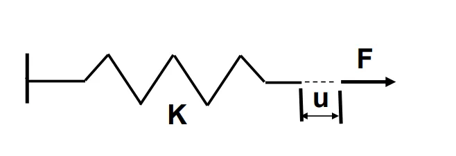
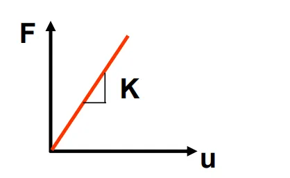
Using Hooke’s Law, linear problems can be understood. For example, a spring element obeys the following equation:
F=K×u
Linear Structures
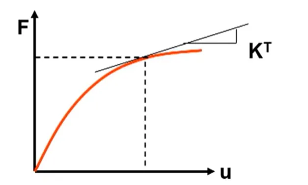
The deformation of a structure and the forces acting on it are always linearly related, and the stiffness of the structure remains unchanged throughout the computation. However, in nonlinear problems, the stiffness of the structure is not constant; it can change due to various reasons. As shown in the figure below, Kt is referred to as the tangential stiffness.
Nonlinear Structures
Causes of Nonlinearity
What factors can lead to nonlinearity in a structure? They include the following points:
- Large deformations of the geometric structure, resulting in stiffness no longer adhering to linear relationships, which is categorized as geometric nonlinearity;
- When the strain of a material exceeds its elastic limit, the stress-strain curve no longer follows a linear distribution; this situation is referred to as material nonlinearity;
- Changes in the state of the structure leading to nonlinearity, categorized as contact nonlinearity.
Thus, nonlinear problems in finite element analysis can be classified into three categories: geometric nonlinearity, material nonlinearity, and state/contact nonlinearity. This article will primarily describe geometric nonlinearity in detail.
II. Geometric Nonlinearity
Before introducing geometric nonlinearity, it’s essential to understand the small deformation assumption in linear problems, which is a prerequisite for elastic mechanics and linear elastic finite element analysis. In elastic mechanics, the small deformation assumption indicates that the deformation caused by external forces is small compared to the object’s original geometric dimensions, allowing the neglect of size changes due to deformation. This enables the use of the original geometric dimensions to establish various equations, while the second-order components of strain can be ignored, leading to a linear expression. However, in practical engineering, many situations do not conform to this small deformation assumption. In such cases, the equations should be established using the deformed geometric dimensions, which includes higher-order terms, resulting in a nonlinear problem.
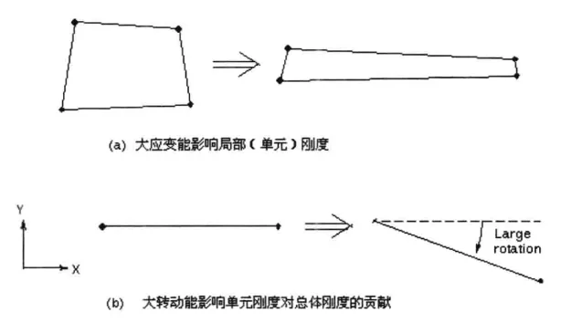
Geometric nonlinearity refers to the nonlinearity generated when a structure or component undergoes deflection due to changes in its geometric shape, meaning that stiffness KKK is a function of displacement uuu. The change in stiffness is due to shape changes or material rotations, primarily manifested as large strains, large displacements, stress stiffening, and rotation softening.
-
Large Strains: The total stiffness of a structure depends on the direction and stiffness of the elements. If the shape of an element changes, its stiffness also changes. If the direction of this element changes, the conversion relationship from local stiffness to global stiffness also changes. The small deformation assumption treats such changes in stiffness as insignificant; however, large strain analysis must consider the changes in stiffness due to shape and direction changes of the elements. This effect can be activated by enabling “large deformation,” with corresponding engineering cases including rubber, foam deformation, and metal plastic forming.
-
Large Displacements: Also referred to as “large rotations” or “small strains,” large displacement analysis assumes that the rotation of an element can be arbitrarily large while the strains are small and there are no significant shape changes. This feature is applicable in all beam elements and most shell elements and is activated by enabling “large deformation.” Corresponding engineering cases include thin-walled containers under pressure, fishing rods, and other slender cantilever beam structures subjected to downward loads.
-
Stress Stiffening: The relationship between internal stress and transverse stiffness is commonly referred to as stress stiffening. Stress stiffening describes the change in stiffness of a component between unstressed and stressed states. In a stressed state, the stiffness in a certain direction of the component significantly increases. For example, the main cable of a suspension bridge or the cables of a cable-stayed bridge have almost zero transverse stiffness when no axial tension is applied; however, when subjected to significant tension, their transverse stiffness increases significantly, demonstrating the stress stiffening effect. The “large deformation” analysis also includes the stress stiffening effect, with corresponding engineering cases including cables and stringed structures like guitars.
-
Rotation Softening: Dynamic mass effects adjust the stiffness matrix of rotating bodies. In small displacement analysis, this adjustment approximates the effect of geometric shape changes caused by large rotational motion. However, it is important to note that rotation softening should not be used in conjunction with other nonlinear effects; it can only be activated during specified rotational modal analyses. Corresponding engineering cases include the modal analysis of gyroscopes.
III. Engineering Analysis
The failure modes of geometric nonlinearity problems in engineering are primarily manifested as instability. So, how should finite element analysis address geometric nonlinearity issues, and in what ways do these analyses differ from linear analyses?
In ANSYS Workbench, compared to linear analyses, the following treatments are required for geometric nonlinearity issues:
1. Preprocessing
Geometric Model
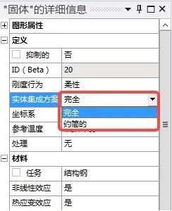
In the geometric model, it is necessary to determine the integration method used for this analysis (full integration or reduced integration), which can generally be left at the default setting.
Change the element control to “manual,” click on the part in the model tree, and choose the integration method.
Mesh Properties
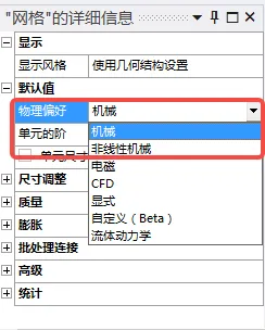
If large strains are anticipated in the mesh, select “Nonlinear Mechanics” when analyzing complex models; the mesh quality will be higher than the default.
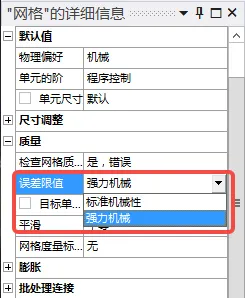
Mesh quality checks can be set to “High-Quality Mesh,” making mesh checks stricter and improving mesh quality.
Note: Mesh settings in geometric nonlinearity analyses are not mandatory and can be adjusted based on actual conditions.
Integration Elements and Element Order:
In linear analyses, the stress and strain results at integration points are extrapolated from nodal solutions; in nonlinear analyses, integration results are replicated from nodal solutions. Full integration can solve most problems but may lead to shear locking and volume locking. To address these two issues, reduced integration is introduced, but reduced integration can also result in hourglass effects. To avoid the hourglass effect, high-order elements or refined low-order elements (with at least three layers in thickness) can be used. When there is only one layer of elements in the thickness direction, using fully integrated elements is beneficial for increasing accuracy. Detailed descriptions of integration methods, locking, and hourglass issues can be found in another article on the blog.
Material Properties
In the absence of material nonlinearity, the settings can remain consistent with linear problems.
Solution Settings
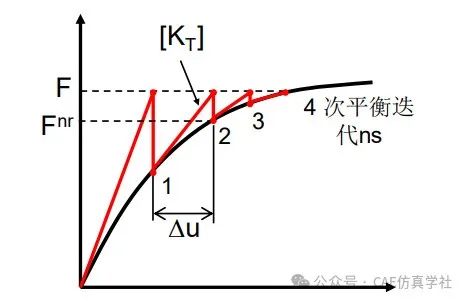
ANSYS uses a linear solver for nonlinear solutions, dividing loads into a series of incremental forms and gradually applying loads, while adjusting the stiffness matrix at the end of each load increment using the Newton method. Therefore, it is necessary to set load increments (i.e., load substeps), solution controls, and convergence criteria.
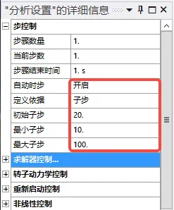
- Step Control: Enable automatic time steps and set initial substeps, maximum substeps, and minimum substeps.
Example: Initial 20, minimum 10, maximum 100, then the first step applies 1/20 of the total load, and each subsequent step applies 1/10 to 1/100 of the total load. When the total load has been applied and converged, the calculation is complete.
Solver Control: Compared to linear analysis, the parameters that need to be set are as follows:
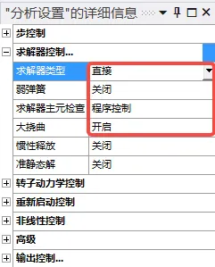
- Solver Type: Direct and iterative methods. The direct method refers to sparse matrix solvers, which have better stability and are recommended for models with stronger nonlinearity and discontinuous elements (shell and beam elements). The iterative method (PCG) is more efficient and is recommended for primarily linear elastic large solid models. When solving nonlinear problems, direct methods or program-controlled options can be used;
- Large Deformation: Large deformation must be enabled in nonlinear analysis. Large deformation is an algorithm that considers the reconstruction of the stiffness matrix after structural deformation. Generally, for ordinary precision problems, if deformation exceeds 5% or rotation exceeds 10°, it is recommended to enable the large deformation switch.
Nonlinear Control
The calculation method and convergence criteria need to be set:
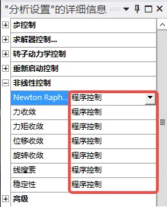
- Newton’s Method: Used to specify the frequency of updating the stiffness matrix during the solution process. The full method updates the stiffness matrix at each iteration, while the asymmetrical method also generates an asymmetrical matrix suitable for cases of strong nonlinearity (e.g., friction coefficients > 0.15). Asymmetrical methods will consume more time and resources than full methods. If convergence is difficult with the full method, switching to the asymmetrical method can facilitate convergence.
- Convergence Criteria: Mainly using force convergence criteria (indicating residual force convergence). Displacement convergence is used for relative detection; when the model involves rotation, torque and rotational convergence are needed. Thus, when analyzing solids or 2D elements, use force + displacement convergence, and for beams or shell elements, use force + displacement + torque convergence. Generally, program control can be used, and when convergence is challenging, force convergence may be retained while disabling others;
- Line Search:
- Stability: Used to address buckling issues and local yielding.
Restart Control: Interrupt the solution, modify the settings of existing parameters, and continue the solution from the saved point.
2. Post-processing
Solution Scheme Information
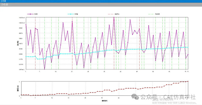
The output information from the solver can be used to view the entire solution process; the convergence information of the force can be used to observe the loading and iteration processes.
Residual Force Review
As shown below, setting the Newton-Raphson residual to 5 allows you to view the residual force calculation results of the last five iterations after the calculation is complete. If the results do not converge, you can identify problematic locations through the residual force contour and make appropriate modifications.
Appendix 1: Newton Iterative Method
In ANSYS Workbench, the computational principle of Newton’s method is illustrated in the diagram below. In the first iteration, the total load Fa is applied. The displacement result x1 is obtained. Based on this displacement, the internal force F1 is calculated. If Fa≠F1, the system is unbalanced. Therefore, based on the current conditions, a new stiffness matrix is calculated (the slope of the dashed line). The value of Fa-F1 is referred to as the unbalanced force or residual force. When the residual force reaches a sufficiently small value, convergence is achieved. Thus, it is necessary to set several substeps within one load step to incrementally load and ultimately achieve convergence.
